
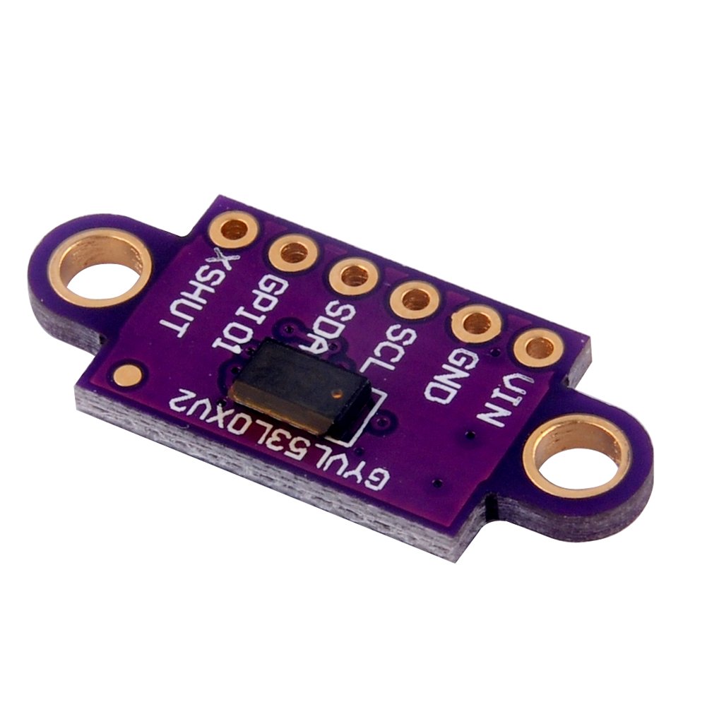


VDD Regulated 2.8 V output. Almost 150 mA is available to power external components. (If you want to bypass the internal regulator, you can instead use this pin as a 2.8 V input with VIN disconnected.) VIN This is the main 2.6 V to 5.5 V power supply connection. The SCL and SDA level shifters pull the I²C lines high to this level. GND The ground (0 V) connection for your power supply. Your I²C control source must also share a common ground with this board. SDA Level-shifted I²C data line: HIGH is VIN, LOW is 0 V SCL Level-shifted I²C clock line: HIGH is VIN, LOW is 0 V XSHUT This pin is an active-low shutdown input; the board pulls it up to VDD to enable the sensor by default. Driving this pin low puts the sensor into hardware standby. This input is not level-shifted. Package includes : 1 X GY-VL53L0XV2V L53L0X Time-of-Flight Distance Sensor
V**R
Best distance sensor for hobby robotics
I got this to upgrade my HC-SR04 ultrasonic sensors and wow, what a difference!This sensor uses infrared laser so it's precise to the millimeter up to 2 meters. In contrast to the ultrasonic, it automatically compensates for surface reflectance and ambient light so there is no jitter, and has a focused beam so no crosstalk between sensors.It has its own embedded controller that takes care of the measurements, no need to mess about with Arduino timer interrupts - in continuous measurement mode you can just take the last reading via I2C bus whenever the Arduino is ready to process it.The I2C lines are level shifted and there is an onboard regulator so it can be connected directly to 5V or 3.3V. It consumes 20mA @5V.To get it running I simply downloaded the Pololu VL53L0X library and used the Continuous example. (I have a Polulu breakout as well, they are compatible and can run side by side).It is also fairly easy to hook up many sensors to the same I2C bus, however you do need to take extra care of the wiring and need an extra pin per sensor for the address initialization. All the sensors have the same factory I2C address, but you can change the address programmatically. To do this you first pull the XSHUT pin to LOW to put all sensors into shutdown, then bring them out of shutdown one by one by setting pinMode(XSHUTn, INPUT), initialize, set unique address and start measuring, then do the same with the next sensor, etc. REMEMBER: ***NEVER*** drive the XSHUT pin HIGH! - it's a 2.8V pin WITHOUT level shifting! It has a pullup resistor on the breakout board to the 2.8V regulator: this why you have to set the pin to INPUT rather than HIGH. That tells the Arduino to just 'let it go'. Be aware there are some sketches floating on the Web for other breakout boards which *do* have level shifting on this pin, make sure you check your code and remove any code that drives it HIGH!
Trustpilot
3 weeks ago
1 week ago
